Choose the right inverter
WTC has more than 20 different sizes and configurations of inverters to suit your needs. Choosing the size of inverter that you need should be one of the
last decisions to make.
The first consideration is determining the amount of weld current and time required for the production of the part that one is welding. The next consideration
is to determine the tooling that will conduct the weld current to the work piece.
Once the tooling is determined, the next consideration is to determine the electrical voltage that is required to push the required current through the circuit.
The calculations will determine all the voltage drops along the path including the voltage drop across the part being welded. The additions
of all of these voltage drops will determine the voltage requirements of the welding transformer needed. The weld transformer will take the incoming voltage from
the inverter weld control to determine a turns-ratio of primary windings to the secondary windings to step down to the proper secondary voltage requirments.
This will finally provide all the necessary information to determine the correct size inverter required for the application.
Zeroing in to the right inverter requires answers to several questions.
Will your application require the inverter to be cooled by water or by air?
What is the incoming primary voltage of the bus that is supplying power to the inverter?
What is the turns ratio of the weld transformer that you are using?
What is the programmed weld current for your application?
If your application is using current/heat steppers to compensate for electrode wear, what is the maximum additional current at the end of the weld?
(expressed in percentage of current from the base current)
You might be welding using pulsation patterns or simply using a single steady current patterns - we need to determine the most intense duty cycle over a four (4) second interval -
so how many pulses are you programming and how many Heat Time milliseconds and Cool Time milliseconds.
How fast is your welder working? What is the shortest time in milliseconds between the start of one weld to the start of the next weld?
How many welds are done on a part?
Finally - how much time between parts? That would be time in milliseconds from the start of one part to the start of a new part.
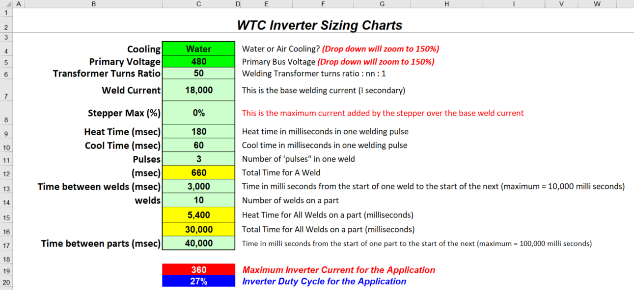
The image below shows what a sample of answering all the above questions.
The chart determines in this case that the maximum current through the inverter for the application is 360 amperes with a duty cycle of 27%.

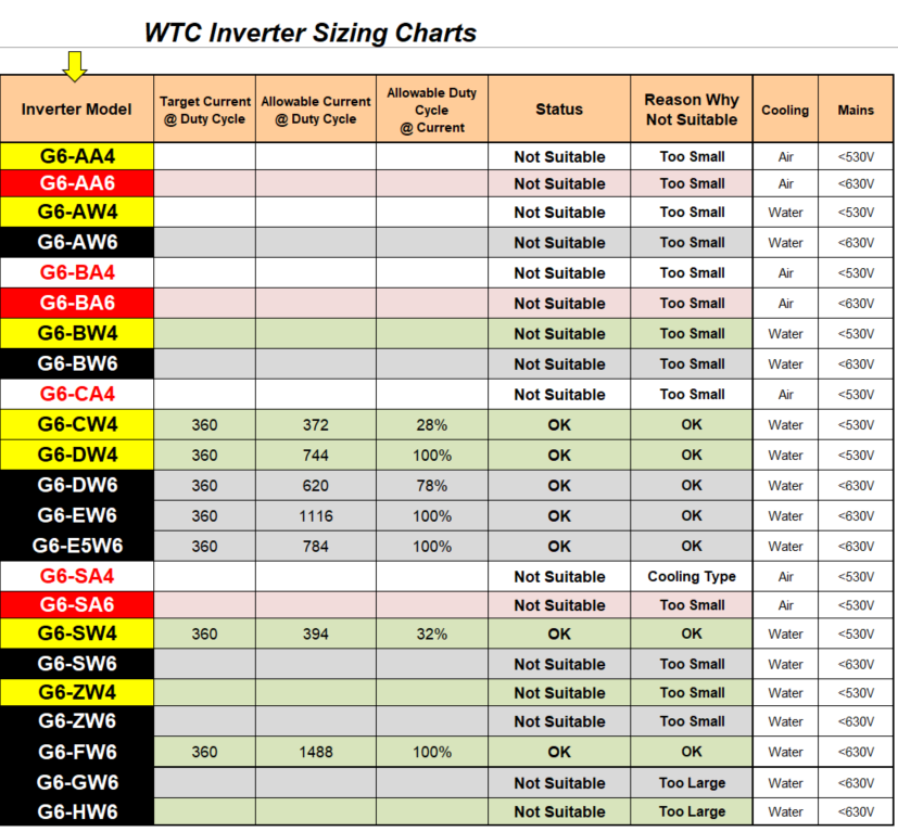
The results of the assembly of questions will lead us to what are appropriate inverters to use. Many of the inverters are not suitable to use based on the input of data -
some are too small and others are too large. Some others might be the right amperage size however they may be the wrong cooling type.
There are in this case seven (7) inverter models that are suitable, each working at a different degree of effort.

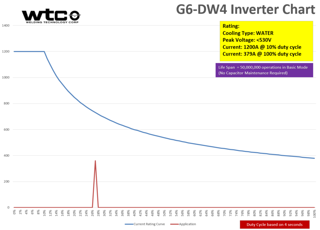
The next size inverter, the DW4 inverter is working with greater ease. The limits of the DW4 is 744A at 27% duty cycle - or if staying at 360A, the welding equipment can only be sped up to operate at 100% duty cycle.
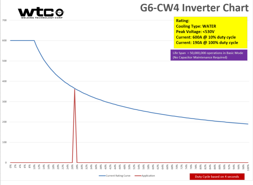
See the CW4 and DW4 operating charts below:
The first chart below is the CW4 chart showing that it is running just within the acceptance curve. There is no problem for using this inverter as operating here - but if you desire at a later time to speed up the line, this inverter will not support the increased duty cycle.

The second chart below is the DW4 chart showing that it is running well within the acceptance curve. There is no problem for using this inverter as operating here - but be assured that you can speed up the line and operate at a greater duty cycle without problem.


