
Special Report - Normalized C-Factor
This application notice is to convey experimental results that would support the concept of using C-Factor information that is reported on the Data Entry Panel to simplify the validation of resistance welding tools.
Present Methodology
Present welding tool validation procedures involve the sequencing of welding controls and verifying that the target currents were obtained within acceptable ranges. What this means is that a person who verifies the capability of the tool will close each welding gun in sequence and determine by a series of experiments that the welding tool is neither undersized nor oversized for the intended applications. Verification that a welding tool is not undersized is accomplished by assuring that the maximum current requirement (which means the heaviest requirement couple with any stepper profile) will be attained below 90 percent of the maximum available current. Similarly, verification can also establish that the welding tool is not oversized by the same series of experiments by assuring that the minimum current requirement will be delivered above 50 percent of the maximum available current. The 90 and 50 percent limits are suggested values and may not take into consideration all conditions. Welding verification teams may want to set their own internal values.
Voltage Supply Problems of Build Area
The present verification method described above requires that the welding supply bus and the temporary hookup of the welding control at the weld tool build site be as rigid as the conditions that will be present at the final plant destination. If tools are built in areas that can not match those conditions, it becomes impossible to verify the tools using the methodology above.Sometimes, welding controls are hooked up using very long cables above the circuit breaker if the welding tool is built in a remote area of a plant that does not have a proper welding bus. What usually happens during verification in such instance is that there appears a large voltage drop along the cable before the welding control when the current draw increases. It becomes impossible sometimes to deliver the current within the 90 percent limit if the voltage drop is significant.
Using Normalized C-Factor for Validation of Welding Tools
As described in other documents, C-Factor represents one-percent of maximum current capacity of a welding tool. C-Factor is determined by the following equation:
C-Factor (absolute) = I (max) / 100 = I (sec) / %I
This equation assumes that the welding bus is constant. It is important to note that the current flow is not only affected by the resistance of the tools but also by the voltage of the bus as expressed by Ohm’s Law; I = E/R. In day to day operations of resistance welding equipment, the resistance of the tooling is the variable of concern. Accordingly, it is useful to "normalize" the C-Factor in order to strictly observe the resistance variable.
The following equation expresses the normalized C-Factor:
C-Factor (normalized) = C-Factor (absolute) x Voltage (nominal) / Voltage (Actual)
If the actual line voltage is equal to the nominal voltage, then the normalized C-Factor is simply the absolute C-Factor. If the actual voltage decreases, then the absolute C-Factor is multiplied by a value that is higher than unity to yield the normalized C-Factor. This "normalization" factor is to determine what the C-Factor would have been if the voltage would have stayed constant.
Experiment – Normalization of C-Factor
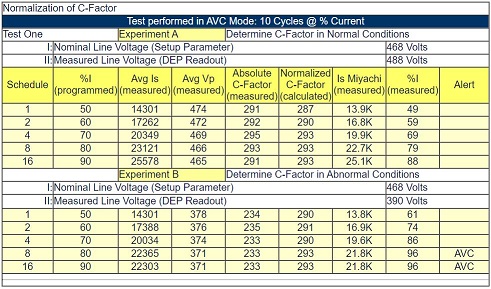
Test Results:Test One – AVC Mode
A MedWeld 3005 control with program T93303-00-01 software was used for the tests. The nominal voltage setting was programmed to 468 volts. Welding schedules 1, 2, 4, 8 and 16 were programmed at 10 cycles of weld at 50, 60, 70, 80, and 90 percent current respectively. A welding transformer with a turns ratio of 63 to 1 was outfitted. For the first set of results (Experiment A), the welding bus voltage of 488 Volts was hooked up to the line side of the circuit breaker. For the second set of results (Experiment B), a step-down transformer was used to bring down the welding bus voltage to 390 volts.All weld schedules were initiated twice with the second results recorded. This was to throw away learning behavior from the control as its environment change significantly in terms of welding bus voltage levels and changing in welding functions from AVC type welds to Creg type welds.
Test One Results and Observations
For each setting, the following information was recorded:i. Average Secondary Current (Avg. Is); this measurement was obtained from the Data Entry Panel.
ii. Average Primary Voltage (Avg. Vp.) ; this measurement was obtained from the Data Entry Panel.
iii. Normalized C-Factor; this measurement was obtained from the Data Entry Panel.
iv. Secondary Current; this measurement was obtained using a Miyachi recorder.
v. Measured Percent Current; this measurement was obtained from the Data Entry Panel
vi. Alert or Fault conditions.
A value called "Absolute" C-Factor was calculated by taking the Average Secondary Current and dividing it by the measured percent current.Observation 1: The Normalized C-Factor values remain consistent at all ranges of percent current regardless of the welding bus voltage. This would be useful for tracking the resistance variable of the Ohm’s law equation. Multiplying the Normalized C-Factor by 100 would obtain the value of the maximum current availability had the welding bus voltage remain at the nominal voltage setting.
Observation 2: The voltage compensation routines prove to be performing well. When the voltage compensation routine lacked compensation room, an AVC alert was enunciated.
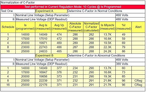
Test Results:Test Two – CREG Mode
A MedWeld 3005 control with program T93303-00-01 software was used for the tests. The nominal voltage setting was programmed to 468 volts. Welding schedules 1, 2, 4, 8 and 16 were programmed at 10 cycles of weld at 14000, 17000, 20000, 23000 and 25000 amperes respectively. These values of current were selected since they approximate 50, 60, 70, 80 and 90 percent of maximum current as determined in Test One – AVC Mode. A welding transformer with a turns ratio of 63 to 1 was outfitted. For the first set of results (Experiment A), the welding bus voltage of 488 Volts was hooked up to the line side of the circuit breaker. For the second set of results (Experiment B), a step-down transformer was used to bring down the welding bus voltage to 388 volts.All weld schedules were initiated twice with the second results recorded. This was to throw away learning behavior from the control as its environment change significantly in terms of welding bus voltage levels and changing in welding functions from AVC type welds to Creg type welds.
Test Two Results and Observations
For each setting, the following information was recorded:i. Average Secondary Current (Avg. Is); this measurement was obtained from the Data Entry Panel.
ii. Average Primary Voltage (Avg. Vp.) ; this measurement was obtained from the Data Entry Panel.
iii. Normalized C-Factor; this measurement was obtained from the Data Entry Panel.
iv. Secondary Current; this measurement was obtained using a Miyachi recorder.
v. Measured Percent Current; this measurement was obtained from the Data Entry Panel
vi. Alert or Fault conditions.
A value called "Absolute" C-Factor was calculated by taking the Average Secondary Current and dividing it by the measured percent current.Observation 1: The Normalized C-Factor values remain fairly consistent at all ranges of current regardless of the welding bus voltage. This would be useful for tracking the resistance variable of the Ohm’s law equation. Multiplying the Normalized C-Factor by 100 would obtain the value of the maximum current availability had the welding bus voltage remain at the nominal voltage setting.Observation 2: The current regulation routines prove to be performing well. When the Creg routine lacked compensation room, a Creg alert was enunciated.
Suggestion for Welding Tool Verification Use
The use of Normalized C-Factor could prove very useful for the purpose of validating resistance welding tools. The person who is responsible for validating can predetermine the acceptable ranges of Normalized C-Factor for tools by the following means:1. Determine the maximum current demand for the tool. This would be the heaviest welding current requirement at the end of the stepper (if used). This would yield the value Is-max (meaning maximum required secondary current)
2. Divide Is-max by 90 to determine the lowest acceptable Normalized C-Factor.
3. Determine the minimum current demand for the tool. This would be the lightest welding current requirement at the start of the stepper (if used). This would yield the value Is-min (meaning minimum required secondary current)
4. Divide Is-min by 50 to determine the highest acceptable Normalized C-Factor.
5. Visit the tool to be validated and ensure that the nominal line voltage that is programmed in the setup parameters is programmed correctly. Sequence the weld schedule. As noted before, it does not matter what the current setting are. The condition of the temporary welding bus is also not much of a factor. Verify that the measured "normalized" C-Factor is between the pre-established limits.
Using tangible values as an example for the above will suffice to simplify the suggestion. Let’s say that a welding tool that needs to be validated is known to require a maximum of 18000 amperes for its toughest job (at the end of its stepper). Let us say also that this welding tool will also require controlling 12000 amperes at its lowest setting. Dividing 18000 by 90 yields a low C-Factor of 200. Dividing 12000 by 50 yields a high C-Factor of 240. This means that in order to satisfy both the over and under sizing issues, the weld tool needs to have a maximum capability between 20000 and 24000 amperes.
To Top