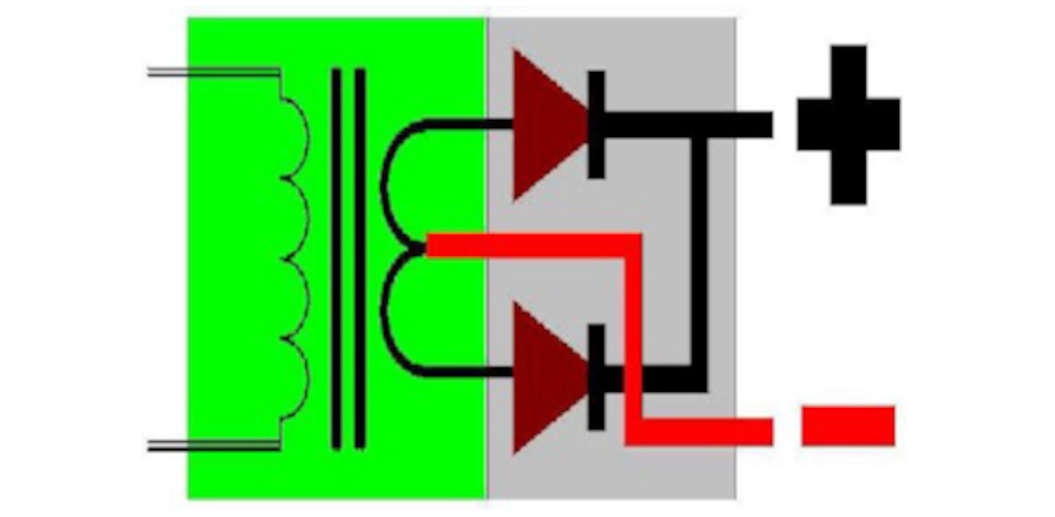
Mid Frequency to DC Welding Transformer
This allows the manufacture of a MFDC power transformer that is the size of a bread toaster. This allows the transformer to be placed much closer to the welding tool in some cases hence providing further benefits. You will see in the MFDC Control section that the switching of the mid frequency pulses is preceded by a fullwave rectifier bridge that converts three phase power supply into a DC bus which is filtered by a capacitor within the control. It appears that the MFDC does not cause line disturbances as is the case with the low frequency DC transformer. In fact, there are advantages for the electrical power supply to install MFDC transformers for resistance welding.
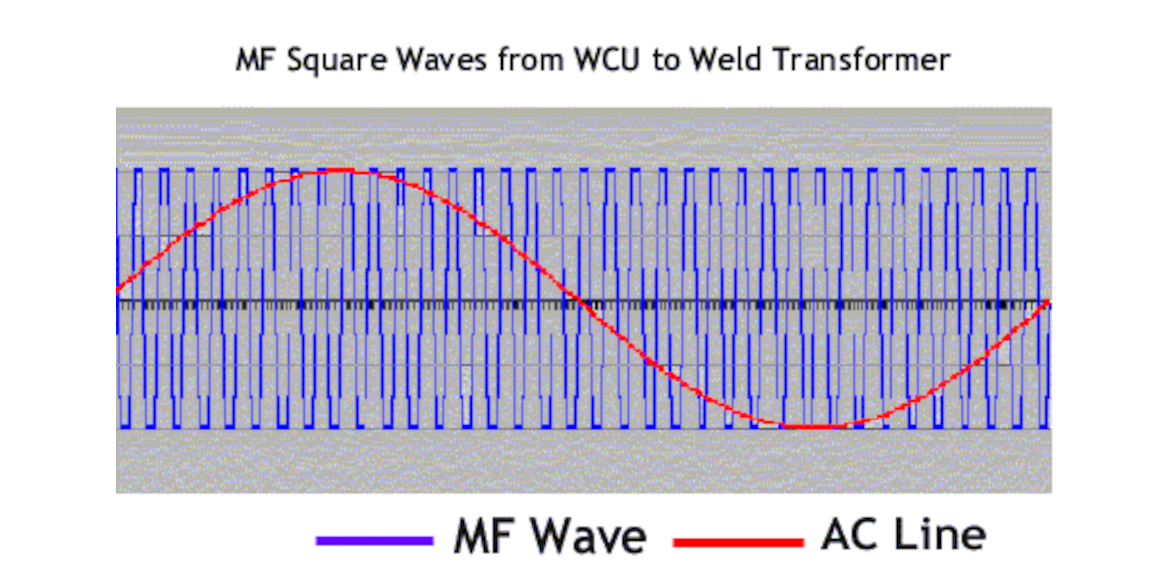
MFDC Current Waveform to Primary Side of Weld Transformer
The output of the MFDC inverter will be squared waves of electrical current at a frequency of 400 to 2,000 Hz. The conventional
output frequency in used globally is 1,000 Hz. The image to the left shows a comparison of a single AC wave (red line) as compared
to that outputted by an MF inverter (blue line).
Comparison of Low Frequence AC Secondary Current to MFDC System
Here you can see a comparison of a Low Frequency AC weld current pattern and an MFDC weld current pattern. If you click on the image
to increase its view size, you can see the details. Both secondary current waveforms are producing equivalent heat energy for
both are outputing about 40kA of RMS current. The major difference is that the low frequency AC has significant inter-cycle cooling
periods so in order to average out to 40kA, the peak output of the AC needs to reach to more than 67kA. For the MFDC system, there is only the starting period for the current to rise where current has not reached 40kA. As a result, the current reaches a peak that is still below 43kA to average out the equivalent output of the AC system above.


